Tuesday, July 16, 2013
While i was playing with my 3d printer printing figures from games, i started thinking about colorful printing just like a typical printer. So first there was the idea of a palette that can hold many colors-hotends. The cam driven extruder (http://www.thingiverse.com/thing:10783, http://www.thingiverse.com/thing:16429) was awesome but i needed it to be in plastic and more "reprapable" than the existing design. I made a mix of them using 608ZZ bearings and herringbone gears. Also i had in mind to use the same motor to select hot-end and to choose filament by using the same degrees of rotation for the cam and the palette, or by adding another gear at the cam that would fix the ratio. The cam drive picks a filament every 36 degrees, and the same degrees are for the palette, to change hot-end. Although i didn't see it working i'm sure it will work. The truth is that i rushed to make it after the finish of the exam period.
Both designs are parametric, but i chose not to put them on customizer because i think they are not ready yet. The scad files here: http://www.thingiverse.com/thing:118542 and http://www.thingiverse.com/thing:118529
The palette
The palette can be mounted easily on a machine with a geared extruder. Just remove the big gear, mount the palette in front of it and then back in place.
It is designed to hold J-head hot-ends because of their weight and reliability. For the bowden cable i decided to go with the snap-fit ones for easy change. Snap-fits are hold with 2 screws. Currently it seems that their hole is a bit small but that gives more pressure on them.
The angle of rotation is varying according to the number of slots the palette has. It starts with 18 degrees for 10 hot-ends (18=180/10) and keep goes. I suggest you choose the 5 hot-ends because the angle is the same for the cam drive too.
Both designs are parametric, but i chose not to put them on customizer because i think they are not ready yet. The scad files here: http://www.thingiverse.com/thing:118542 and http://www.thingiverse.com/thing:118529
The palette
 |
| The palette - looks huge on a printrbot :) |
 |
| Adding some teflon tape for testing |
The angle of rotation is varying according to the number of slots the palette has. It starts with 18 degrees for 10 hot-ends (18=180/10) and keep goes. I suggest you choose the 5 hot-ends because the angle is the same for the cam drive too.
At first the idea was to change the distance between the 8mm axis and the hot-ends, but the distance came out to small for some numbers so i chose to give a default. Currently the surface seems big for the 4mm tubes 'cause they bend easily, but i'm not sure about the 6mm ones.
The scad file i believe it's understandable at least in contrast with the ones for the cam driver..
The scad file i believe it's understandable at least in contrast with the ones for the cam driver..
Multiple & Parametric CAM driven extruder
In order to feed the palette i needed an extruder that could handle it's potential. So the cam came in handy, previous version of a cam driven extruder (link) was not meant for printing. I based on it and on the first idea to make mine, but it needs optimization.
This one is also parametric, as i started designing them at the time customizer challenge was on, but couldn't finish them. Print two motor mounts and two idlers and you can choose as many as ten filament feeds (well, not true cause it needs some fixing in the scad file..).
Number ten comes out of 36*10, as the angle between different filaments. I used a simple motor mount, but after printing and assembling it, many other mounts can be used with a little modification.
I used 608ZZ bearings to push the filaments on the hobbed axis, with this one snap-in holders. They seem pretty good and rolled on the desk while i was pushing them with my hands.
The 3mm screw above helps to keep them aligned so they have an offset of 36 degrees Also between the two ends of the snap-in you can fit a nut and a washer, one with small diameter to make room for the screw.
Place the cam between a motor mount and an idler, making sure your axis is going no further than a slim nut because it will interfere with the big gear from the extruder.
I printed 3 filament feeders in one to check them. They need some tinkering in order to work. I'll try to fix that in the scad file.
In order to mount the snap-fits i used a threading. The hobbed axis is made with a slim cutting disk on my dead dremel and a 8mm threaded rod. It seems to grip well against my hand but a true print will tell.
You can assemble the extruder and the cam apart, and then join them. That way you are able to change the distance between the cam and the extruder and thus the force the bearings exercise on the filament according to it's diameter.
If you want more or less filaments just split it apart. There are two 4mm threaded rods that keep each part in place. You don't have to print again the parts (just the snap-in bearings holders).
I used 4 bearings for the axis's and three more for the cam. The whole thing will need less than a meter 4mm threaded rod to keep everything in place.
The following video is the extruder hand driven, and below through pronterface.
I connected the palette's motor and the cam motor on E1 and the extruder at E0. For the firmware i used Marlin. In order to get it working you change tools with T1 to select the cam and then move it a bit to select desired filament. Then back again to T0, to get the extruder running. It was supposed to move the cam and the palette by the same degrees and thus align the hotend and pick a filament, but maybe it's my bad herringbone gears that caused the problem.
For more filaments-hotends a gear with the cοrrect ratio is needed at the cam, in order to select a filament while the palette may turn at 18 or 72 degrees.
more photos
https://drive.google.com/folderview?id=0B62qBd9fuiOmYmMxUmpwVU9jQ3c&usp=sharing
 |
| cam driven extruder |
In order to feed the palette i needed an extruder that could handle it's potential. So the cam came in handy, previous version of a cam driven extruder (link) was not meant for printing. I based on it and on the first idea to make mine, but it needs optimization.
This one is also parametric, as i started designing them at the time customizer challenge was on, but couldn't finish them. Print two motor mounts and two idlers and you can choose as many as ten filament feeds (well, not true cause it needs some fixing in the scad file..).
Number ten comes out of 36*10, as the angle between different filaments. I used a simple motor mount, but after printing and assembling it, many other mounts can be used with a little modification.
I used 608ZZ bearings to push the filaments on the hobbed axis, with this one snap-in holders. They seem pretty good and rolled on the desk while i was pushing them with my hands.
 |
| snap-in 608zz holder |
 |
| snap-ins with alignment hole |
Place the cam between a motor mount and an idler, making sure your axis is going no further than a slim nut because it will interfere with the big gear from the extruder.
I printed 3 filament feeders in one to check them. They need some tinkering in order to work. I'll try to fix that in the scad file.
 |
| filament feeders, after removing some plastic in the way of the bearings |
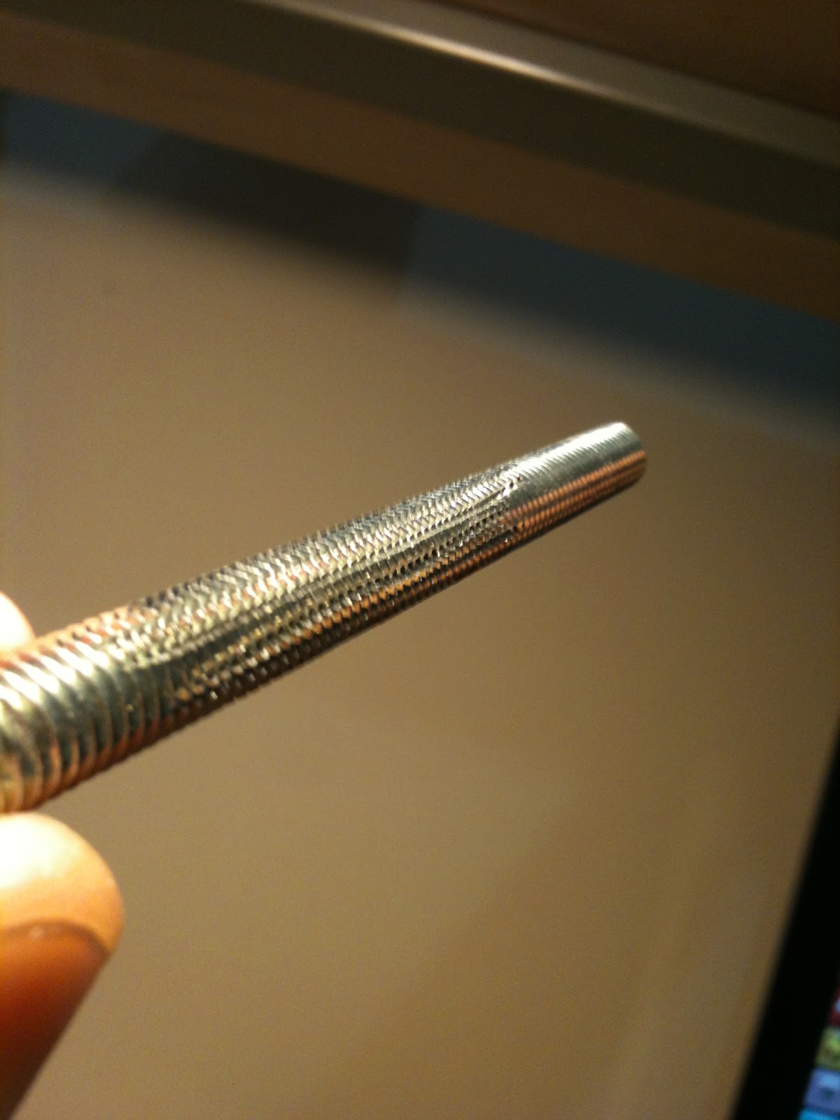 |
| "hobbed" axis, without a vice |
You can assemble the extruder and the cam apart, and then join them. That way you are able to change the distance between the cam and the extruder and thus the force the bearings exercise on the filament according to it's diameter.
 |
| offset between the cam and the extruder, |
I used 4 bearings for the axis's and three more for the cam. The whole thing will need less than a meter 4mm threaded rod to keep everything in place.
The following video is the extruder hand driven, and below through pronterface.
I connected the palette's motor and the cam motor on E1 and the extruder at E0. For the firmware i used Marlin. In order to get it working you change tools with T1 to select the cam and then move it a bit to select desired filament. Then back again to T0, to get the extruder running. It was supposed to move the cam and the palette by the same degrees and thus align the hotend and pick a filament, but maybe it's my bad herringbone gears that caused the problem.
For more filaments-hotends a gear with the cοrrect ratio is needed at the cam, in order to select a filament while the palette may turn at 18 or 72 degrees.
more photos
https://drive.google.com/folderview?id=0B62qBd9fuiOmYmMxUmpwVU9jQ3c&usp=sharing


